

Nowadays, „multi-zone” heating systems are widespread, but with multiple circuits (i.e. separate control of multiple rooms), it is essential to control the appropriate room temperature. We offered our client several options, and in the end, he chose the Honeywell EvoHome package. Since we already had experience, we confidently started the installation. It is important to note that we only installed the control. Like all work, this one also had surprises, but let's proceed in order... The first step was ordering the devices:
- HONEYWELL ATP921 WIFI EVOHOME BASIC PACKAGE (RF relay, WiFis central unit with display and thermostat)
- HONEYWELL MT4-230-NC VALVE ACTUATOR MOTOR (8 pcs, I'll explain why below.)
- HONEYWELL T87 SMART THERMOSTAT (3 pcs)
- HONEYWELL HCE ZONE CONTROLLER FOR UNDERFLOOR HEATING (zone controller, 8 zones) (HCC version includes antenna)
- HONEYWELL HRA EXTERNAL ANTENNA
- HONEYWELL ATF800 DESKTOP STAND FOR ATC928 WIFI EVOHOME ZONE MANAGER
Now all I had to do was place the order at evohomeshop.
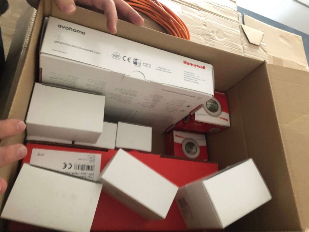
The question may legitimately arise as to why 8 valve controllers were needed if we only wanted to control 4 rooms. Before answering, let's take a look at the heating manifold.
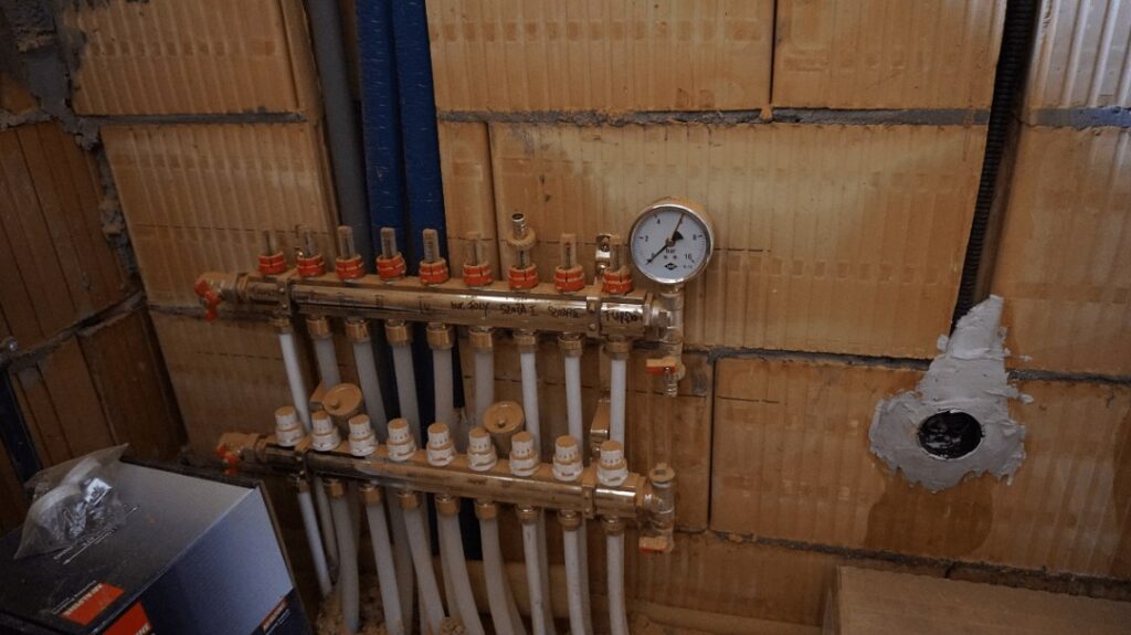
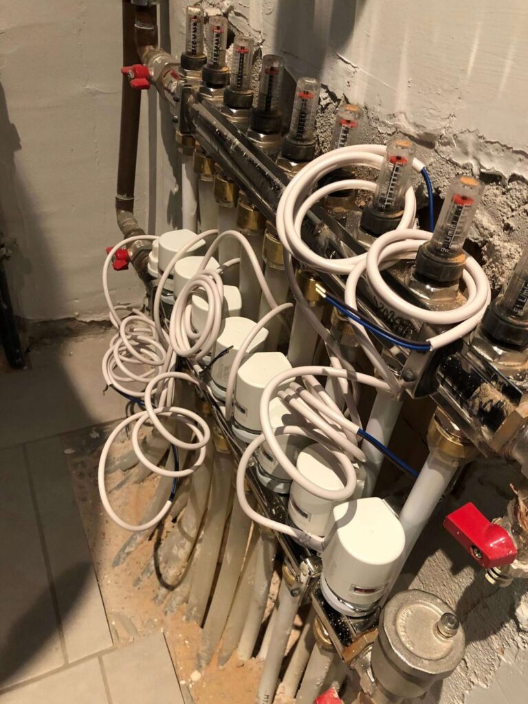
The picture shows 9 circuits, but one of them was not used in the end, so we can count on 8 circuits. However, these 8 circuits supply the heating of 4 rooms. A total of 4 circuits for the living room and dining room, 2 for the bathroom and laundry room, 1 each for the two rooms. It is important to coordinate these before we want to automate, since the Honeywell HCA zone controller can handle a maximum of 3 circuits in a zone. It is also clear from this that we will have to improvise a little here. But let's get back to the subject, so we have 8 circuits for 4 zones and that is why we need the 8 valve control motor. It is important that the heating was designed this way from the beginning, as can be seen in the picture from the junction box placed next to the distributor collector, which is necessary to supply the controller with energy. Of course, it is possible to solve it without this (extension, cable duct, but if we can, then the junction box and planning in advance are the best solution). We cannot emphasize the importance of planning enough; we had to assess what kind of boiler we wanted to control, how much space there was for installation, whether there was a suitable electrical outlet for power supply, etc. However, we went through these in detail, so we started the technical tasks with all the necessary knowledge.
Let's start by removing the manual heads and installing the thermoelectric valve controllers.
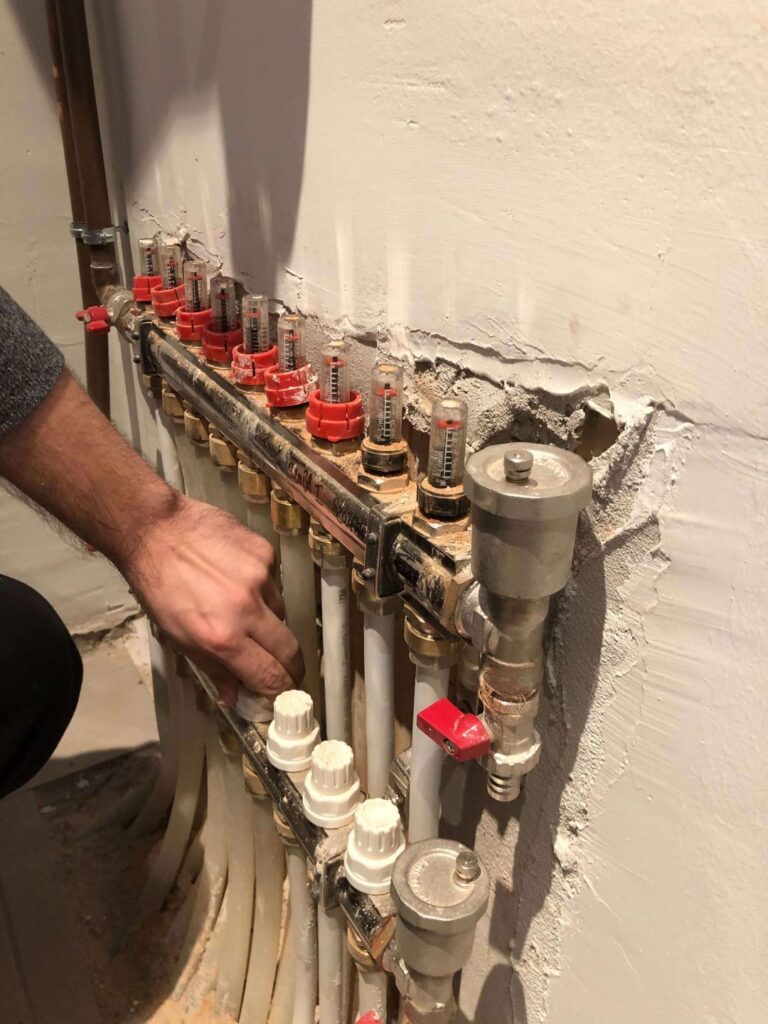
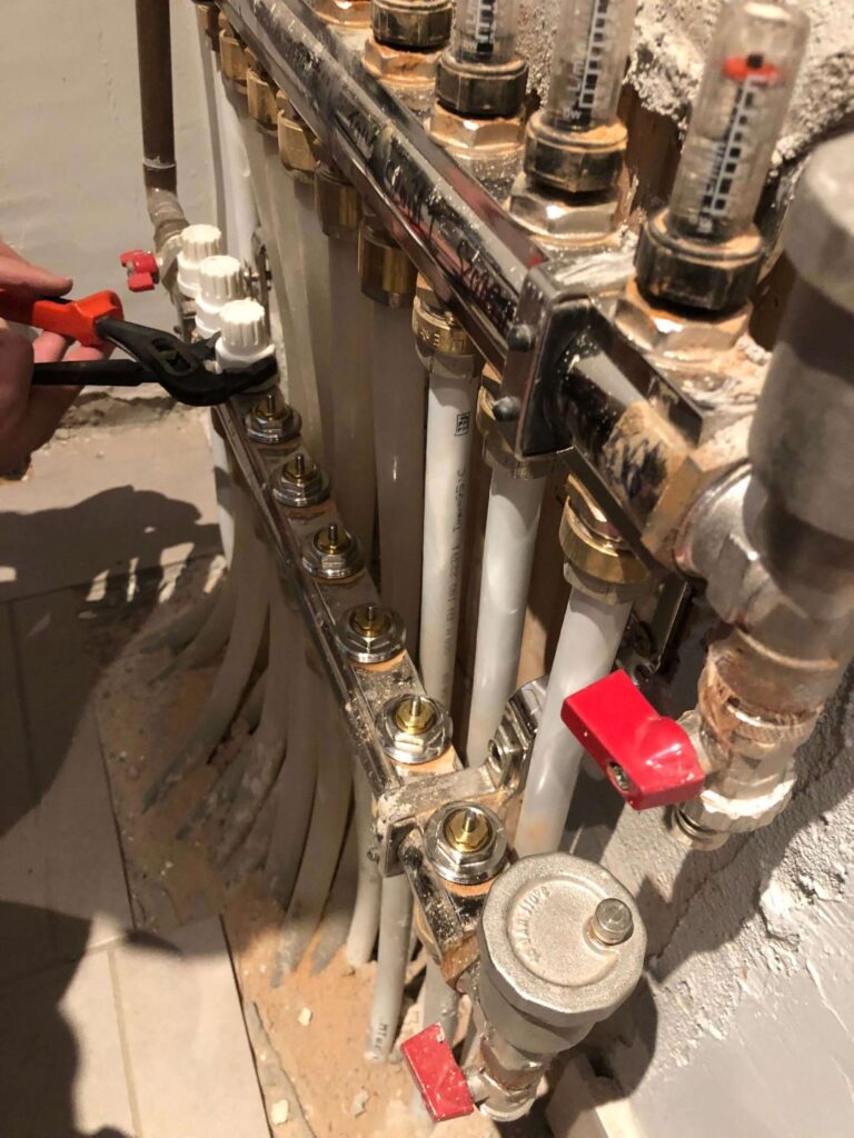
Then we can start heating up the thermoelectric heads. It may happen that if the head is too large or the manifolds are close, they will not fit. In such cases, there is no need to despair, the manifold can always be turned outwards a little. Before choosing valve controllers, it is important to check the size of the valves, as it is unpleasant if we have bought one and only later find out that the diameter is not suitable. There are two types of thermoelectric valves: normally open and normally closed. Whichever one we decide on, it is important that they are all of the same type. In this solution, we chose normally closed, despite the fact that the heating contractor did not install a bypass circuit, which is usually recommended in order to protect the boiler pump. The system is reliable even without a bypass circuit, but we believe that it does not hurt to be protected from several sides, but this may be due to our excessive engineering thinking. The controller normally ensures that the valves are not accidentally closed on all circuits when the pump is running.
The installation itself is not a problem, but the arrangement of the wires can be a challenge with 8 heads. In our case, the moderately nice cable arrangement is not a problem, since the mechanical system will be hidden by an elegant wooden box at the end. Regardless, we tried our best.
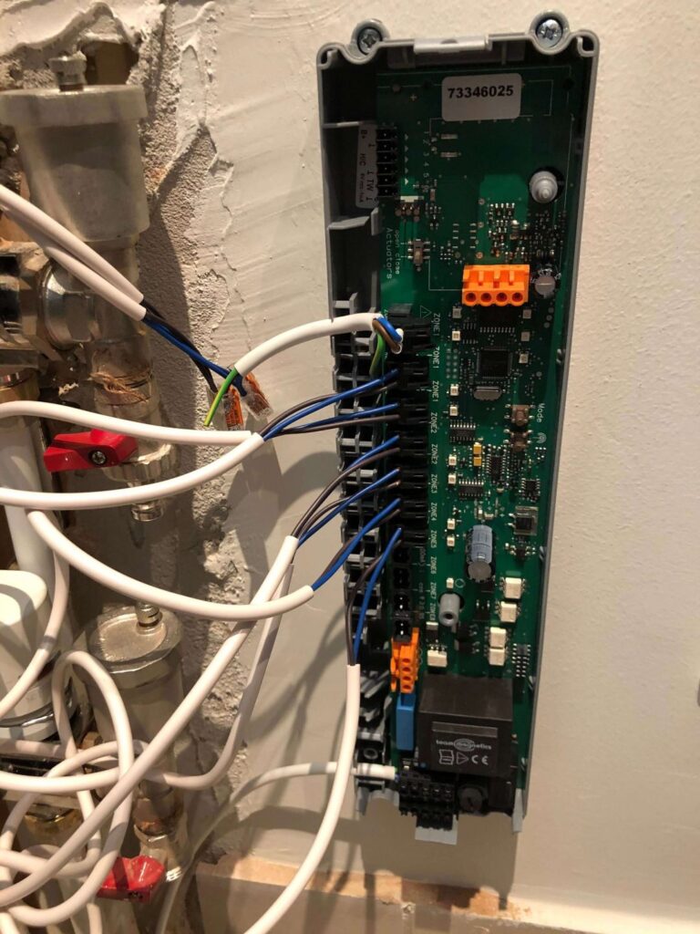
The next step is to install the controller and connect the appropriate zones. We placed the zone controller unusually on the side for the following reasons: the customer requested it, the location of the pipes in the wall and since it is a dry system, moisture should not be a problem. Since the living room and dining room are one zone with 4 circuits, we were forced to use wago to make 3 zones out of the four. This will not have a big disadvantage, the only thing is that 2 control motors will actually be controlled at the same time, since we measured it, and the output power should be sufficient for 2 valves.
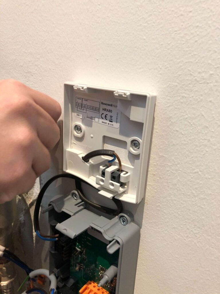
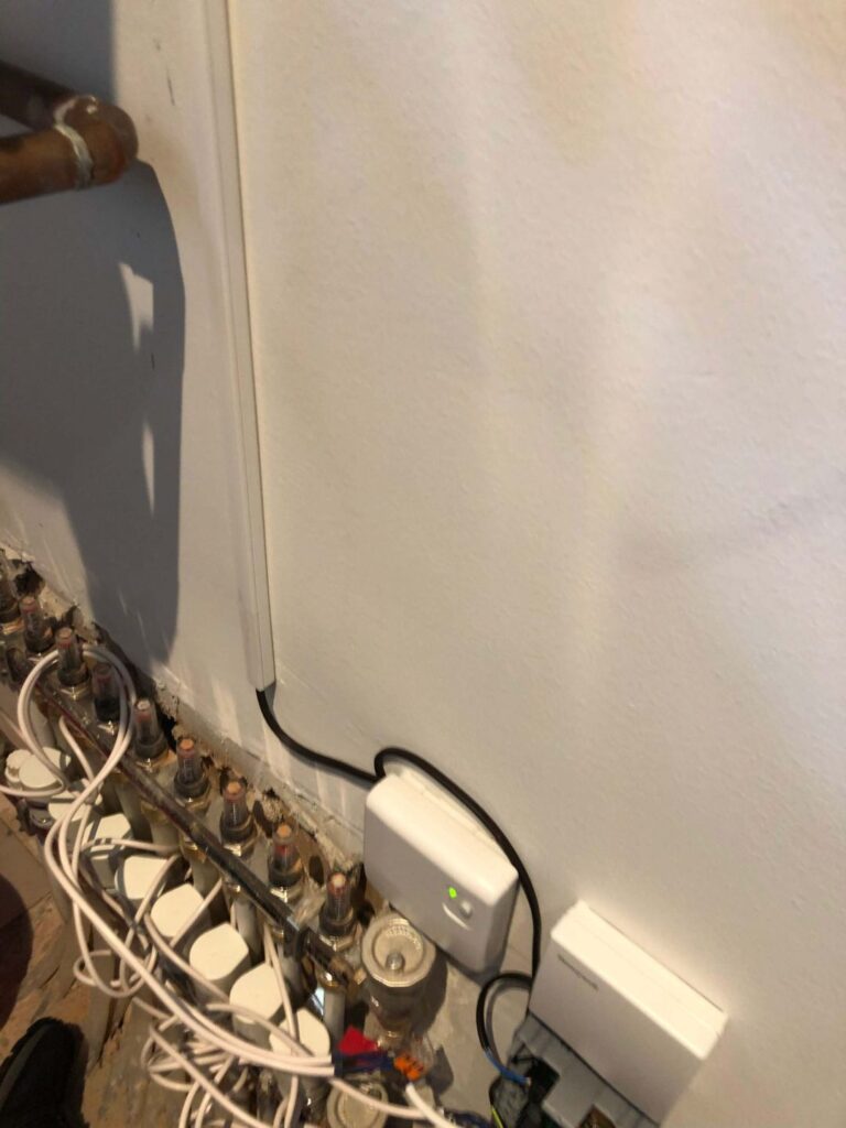
The external antenna can be installed. The antenna connection is not complicated (two wires 1-2), but if you do make a mistake, there is no reason to panic, as the red status LED on the controller will indicate an antenna error. In this case, the easiest way is to change the connection on the controller side.
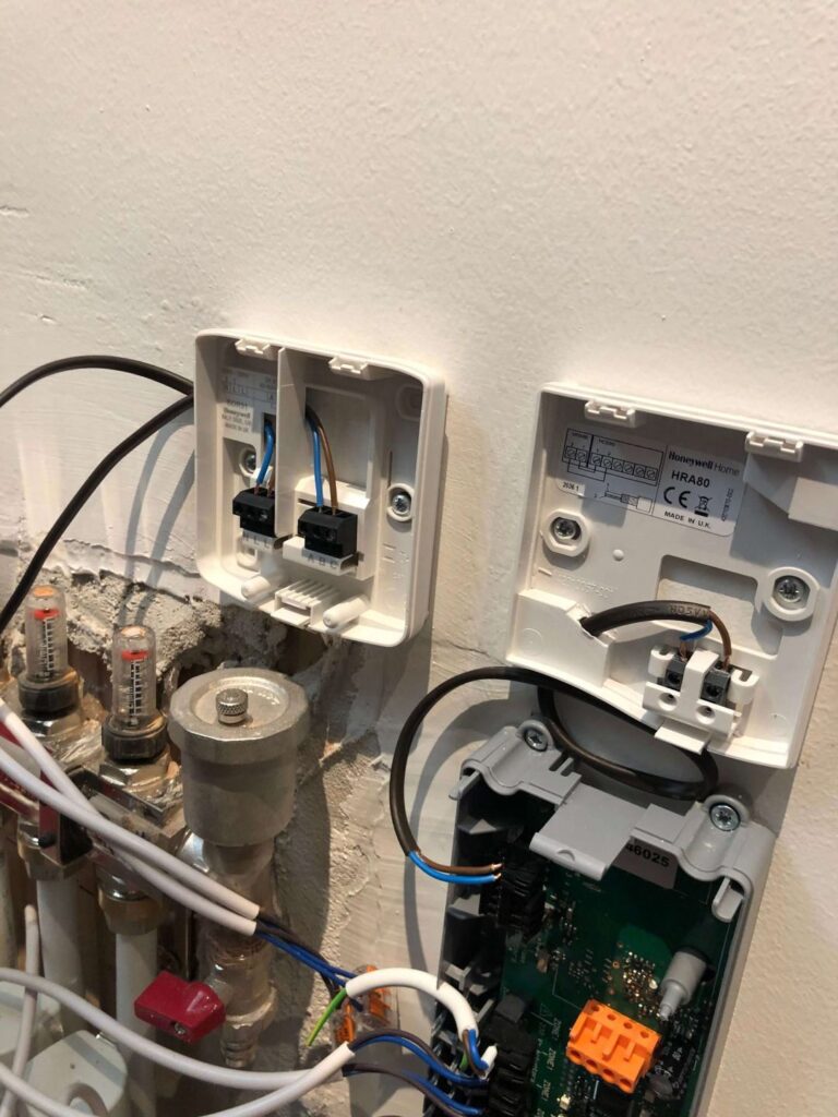
Then we can connect the relay, which will switch the boiler on. We placed it next to the antenna for aesthetics, but it could also have been next to the boiler, since it needs to be connected to the boiler's control input.
After that, the cover was put on the controller. Then we could start teaching the zones and assigning the thermostats to the zones. We haven't connected the boiler yet, so that if we have calculated something, we don't overload the pump unnecessarily.
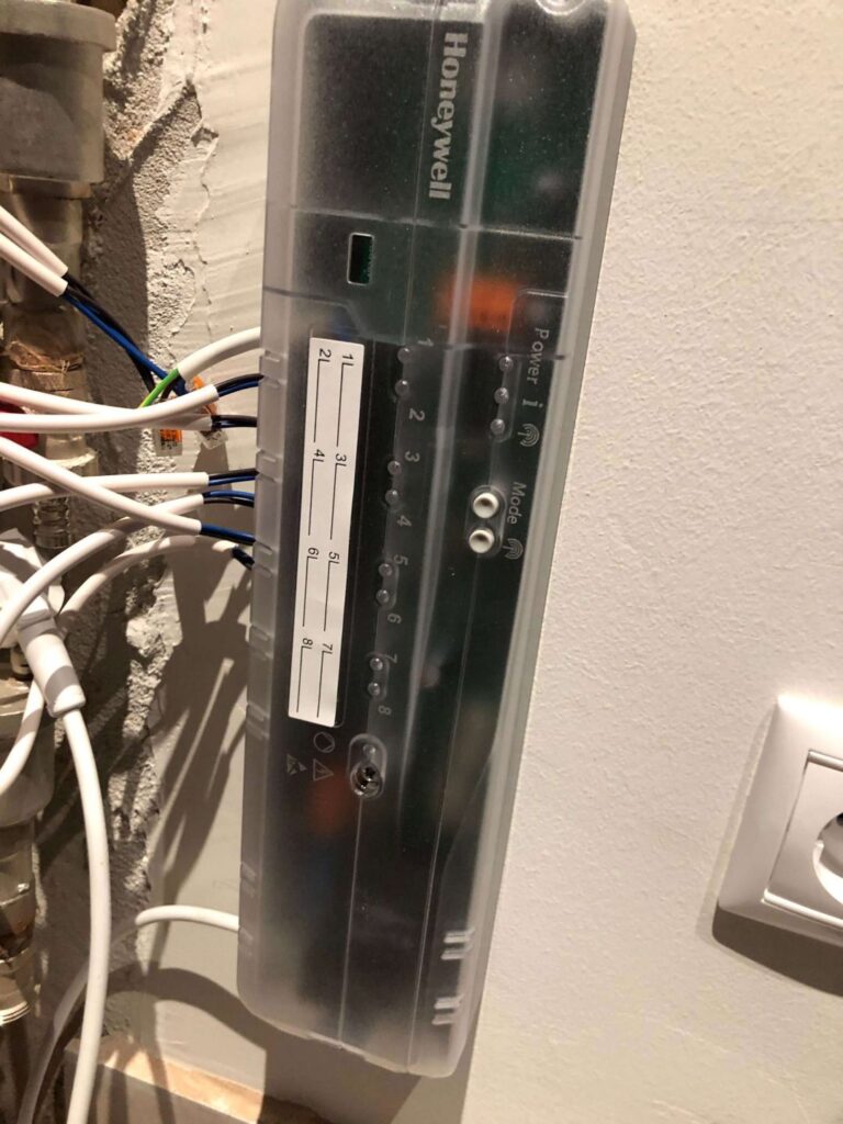
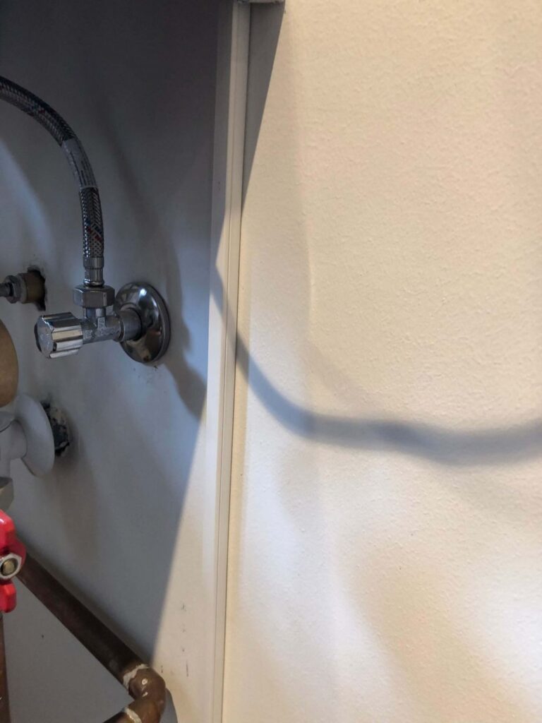
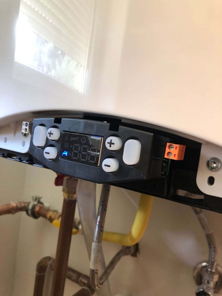
Then comes the training, be patient because of the hysteresis of the thermoelectric valves and the controller, this can take a while, as it takes a few minutes for a valve to open. Testing all the circuits with 4 circuits can easily take 15-20 minutes. After successful training, the next step is to connect the boiler and test the zones. Reading through the boiler's wiring diagram, it turned out that the control input is located on the left side after removing the front panel, so the wires had to be routed there from the relay. We solved this with a very thin cable channel that can be glued to a white wall, so that the black cable routing on the freshly plastered wall would cause as little visual stress as possible.
Configuring it under Home Assistant is the topic of another post. We hope that the information we shared in this short summary was useful. We will try to come up with detailed installation reports on all areas in the future. Our next post will show the installation of an 8-camera system. If you have any questions about smart home, don't hesitate to write to us!
The Yabune Home team.