

The task …
Yabune Home primarily deals with the integration of wireless systems. In most cases, we recommend one of the WiFi, Zigbee and Z-wave protocols to our customers. However, there are cases when a wireless system cannot be easily implemented, either because the given devices do not support it, or because there is already an established wired infrastructure and creating a wireless network would cause unnecessary additional expenses.
In this blog post, we present the modernization of an entire office and site's climate control system with the Yabune Home system. Our client contacted us to make the climate control of their office building and other buildings smarter.
The following climate system was given:
- 2 Daikin VRV heat pumps
- 18 indoor ceiling-recessed units
- 16 wall-mounted wired hand controls
The Daikin system was installed about 10 years ago, and the two heat pumps were replaced with newer models 1 year ago. First, we assessed the needs of the customer, which were as follows:
- Remotely control current climates per room
- Monitoring temperature values
- Expandable center later
First, we assessed our options for smartening up. To do this, we contacted the With Daikin Hungary Ltd., since no one knows Daikin heat pump control better than them. We were not disappointed, they were extremely helpful and quickly brought us to the right level with the help of their experts. During the discussions, it became clear that one of the possible and economically profitable solutions is control via ModBus.
There were several arguments in favor of ModBus, but the two most important ones were that Home Assistant natively supports both ModBus RTU and ModBus TCP, and that purchasing and controlling the Daikin EKMBDXA ModBus adapter seemed like a realistic task.
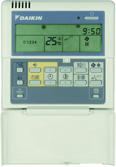
As I mentioned earlier, the system installed at our client is industrial-sized (18 indoor units and 2 heat pumps) and the ModBus adapter had to be purchased, since they did not originally have it. However, in order to figure out the infrastructure, we had to understand how the control currently works. A BRC1D52 wired controller took care of the regulation in each room. Unfortunately, these devices are not very smart, but they came in handy so that the possibility of manual intervention would remain even after automation.
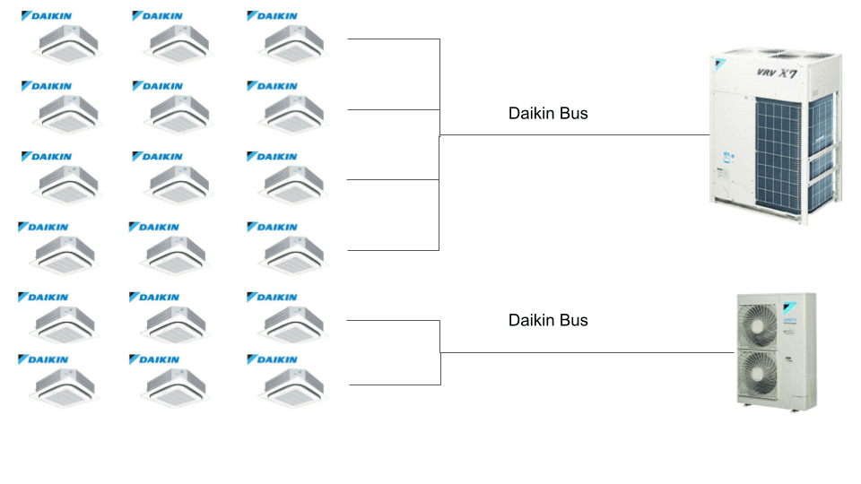
We had to assess with the help of a Daikin expert how the control works in the current solution. As we learned, in the case of Daikin's Bus protocol, the devices placed on the ceiling communicate with the outdoor unit and 12 units are connected to the larger heat pump and 6 to the smaller one.
Something like this:
The theory...
In order to be able to control the system via Home Assistant, we had to solve the problem of being able to address and control the devices via ModBus. Daikin has several solutions for this, one of which is Daikin RTD-NET Control Interface, which, when installed in front of each indoor unit, allows us to control them via ModBus. This is worth it for 2-3 ceiling cassettes, but for 18 it means a serious additional cost, so we were forced to look for another option. We are grateful to the Daikin experts again, as they directed our attention to the Daikin EKMBDXA ModBus adapter. This device directly translates the ModBus protocol to the Daikin internal Bus protocol. It was designed for direct BMS (building management system) systems. Its price is accordingly quite high, but for 18 indoor units it is already worth it.
Based on this, we started to figure out the architecture, which should look something like this:
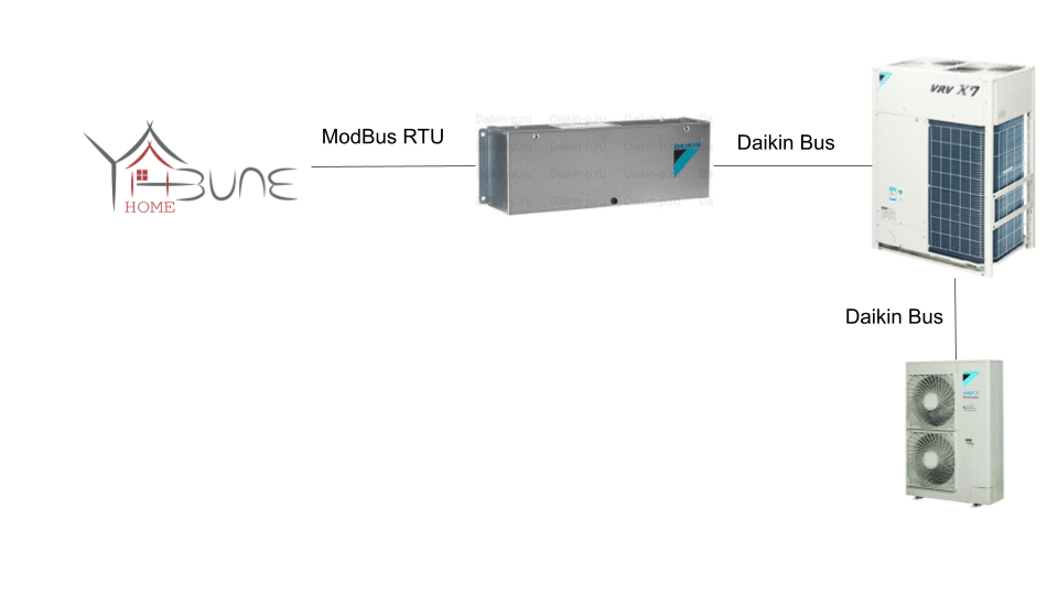
ModBus communicates on a register basis, like most bus-based solutions. Each device has one or more input and state registers. The former can be used to enter values for control, while the latter can be used to read values such as status or temperature. In order to control the ceiling-mounted units, they must be addressed. This is described in a fairly understandable way in the Daikin user manual, but we were not surprised when reading the instructions that this task was clearly not designed for end users. Once the units have been addressed and the ModBus Adapter is functioning properly, the next step is to integrate them into Home Assistant. There is HA ModBus integration, but it doesn't cover all our needs, but it can be expanded relatively with scripts and templates. From here on, what we need to do became clear.
1. Review ModBus Documentation
Every ModBus implementation is different, so we had to review Daikin's own ModBus Design documentation. It describes exactly how and at what register addresses the values of the devices can be read and controlled.
This documentation HERE available.
2. Connecting the ModBus Adapter
The ModBus Adapter must be connected to the two heat pumps in series with a plain two-core 0.75 wire. Once this is done, connect it to the server running Yabune Home via a serial port (e.g. USB adapter).
The starting register address must be set on the ModBus Adapter using DIP Switches. This can be described using the documentation shared in the previous section (1.3.2 Wiring Diagram).
3. Addressing indoor units
The wall controller is used to set the address of each panel. The EKMBDXA Adapter supports a total of 16 devices in 4 zones, in this case we had to configure 18 devices, but this also took a significant amount of time, as the cumbersome sequence had to be done in each room.
4. Install and configure Home Assistant
We installed the Home Assistant-based Yabune Home system on the client's own server at their request. We also prepared a detailed protocol of the process, as this was also expected from the infrastructure operators. I will discuss ModBus integration in more detail in the implementation chapter.
5. Full system testing
After everything is set up and configured, before handover, we of course need to check that everything works as planned. It is important to note that ModBus writes to EPROM, so you can't write the input registers endlessly, so we had to come up with fail safe solutions and test them.
The implementation …
The two heat pumps can be connected in series to the adapter, while the adapter, using ModBus RTU, was connected via a serial port to the server in the server room housing the Yabune Home center. The wiring solution was cumbersome, since the two heat pumps were 30 meters apart, in the open air. When routing the cable, attention had to be paid to adequate weather protection and an aesthetically pleasing solution.
Distance was not really an issue, as we could take the Daikin Bus protocol up to 1000 m before cable loss became a problem.
After the proper wiring was solved, the next step could come. Addressing the indoor units via Modbus. Since the controller had just been installed, the devices installed in the ceiling did not have any identifiers that we could refer to in Home Assistant. This is a step that must be programmed via each wall controller. We placed the devices in a separate Group for each level. A maximum of 4 groups can be set and 16 devices within them, i.e. a total of 64 indoor units. This is the limitation of the controller, but in our case it proved to be more than enough. Here we also relied heavily on the Daikin Hungary expert, as the description is detailed, so it is not always completely clear and it is better to ask him. After we managed to set everything on the controllers, we could proceed with the Home Assistant configuration.
First of all, the configuration.yaml had to be updated to add the modbus module and its devices/sensors. The code below shows this detail. First, we need to specify the Modbus master access, which in this case was connected to the control panel via a serial port (method: RTU and type: serial). The serial transmission was solved with an RS-485 to USB converter, so the port attribute must be set to the USB device address. The further settings were made according to the data sheet of the Daikin control panel. According to the latest HA settings, the air conditioners, binary and simple sensors were classified under the Modbus component.
And then here the code snippet too:
modbus: - name: daikin type: serial method: rtu port: /dev/ttyUSB0 baudrate: 9600 stopbits: 1 bytesize: 8 parity: E climates: !include_dir_merge_list packages/daikin_climate_modbus/climates sensors: !include_dir_merge_list packages/daikin_climate_modbus/sensors template: !include_dir_merge_list packages/daikin_climate_modbus/binary_sensorsThose with an eye for detail can quickly spot that the binary sensors are not under the modbus component. This is not a mistake, as they are nothing more than template binary_sensors. More on this a little further down.
The concept is extremely simple, first we added the climates to the Home Assistant documentation The corresponding parameters and register addresses are given in the Daikin Modbus Interface Design GuideWe looked out of.
Also, in questionable cases, we consulted with a Daikin expert.
To query the operating status of indoor units located in different rooms, we created binary_sensor entities to query various parameters, such as the temperature measured by the unit, the target temperature set by users or automation, and the status word read by the control panel.
The binary_sensors are actually templates that translate the status sensor value into the corresponding binary value, according to the documentation.
Here is an example of two room climate entities (there were 16 of them in total):
- name: Emelet_targyalo_klima slave: 15 data_type: uint data_count: 1 scale: 0.1 offset: 0 precision: 1 max_temp: 30 min_temp: 15 temp_step: 1 target_temp_register: 2053 address: 2106 input_type: input - name: Emelet_sales_marketing_iroda_klima slave: 15 data_type: uint data_count: 1 scale: 0.1 offset: 0 precision: 1 max_temp: 30 min_temp: 15 temp_step: 1 target_temp_register: 2056 input: 2112 input_type: inputEach climate entity required binary sensors and sensors, with different values and states reported by the devices. Examples of these were:
- Set temperature value
- Current measured temperature
- Climate status (we extracted the On-Off status using bit operations)
- Current climate mode setting
Here is an example of how we read the exact operating state from the sensor value with a templated binary sensor:
# sensor example: - name: Floor_topic_status hub: daikin slave: 15 register: 2102 register_type: input # binary sensor template - binary_sensor: - name: "Floor Meeting Room Air Conditioning Status" state: >- {{ states('sensor.floor_topic_status')|int|bitwise_and(1) > 0 }}After we managed to set up all the entities, we used auto entities to display the control tiles of the office rooms on the interface level by level.
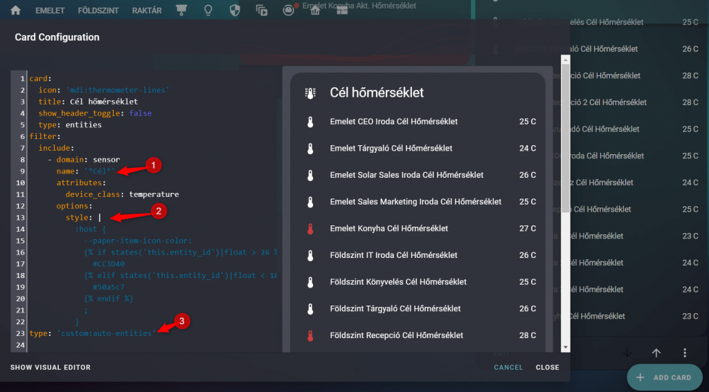
This is the best solution when you need to display a large number of similar sensors, switches, or devices. The filter field allows you to filter based on multiple criteria, such as the device_class or the friendly_name of the device. The style field also allows you to introduce unique colors, such as in this case, if the value is above 26 degrees, the thermometer should be red.
Auto-entities are not only good for bulk listing of devices, but also for aggregated graph cards, for example. See the image below.
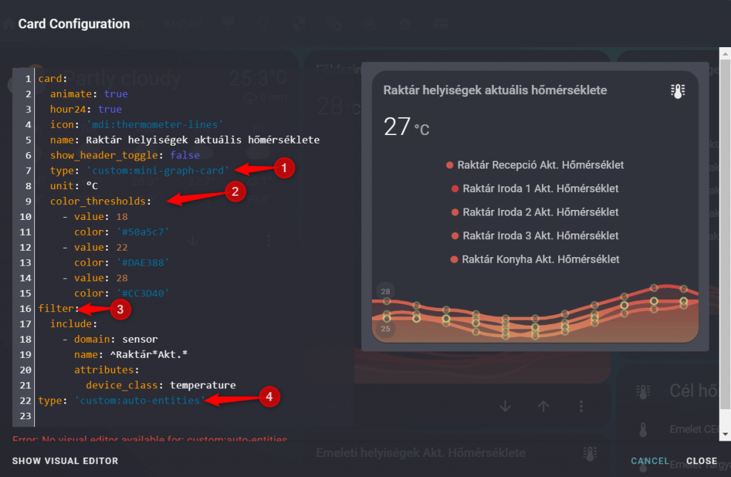
Here we obviously took advantage of the possibilities offered by the graph-card with temperature-dependent coloring. We created a separate card for each level, on which the temperature changes in the rooms can be visually monitored.
When displaying the indoor units, the following solution was chosen. This is the mini-climat card. We also thought a lot about the simple-thermostat card, but in the end this seemed the most elegant.
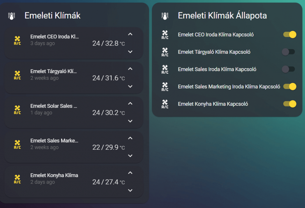
The specific nature of the system required a separate switch panel, because although the air conditioners operate automatically according to the set target temperature, this can be eliminated by switching off the panel placed on the wall. For this reason, we also introduced the remote switching of the wall panel and its status feedback.
The customer can study the data coming from the sensors in detail on the Influx DB and Grafana interfaces we provide. We are currently working with an energy colleague to filter out as much useful information as possible from the accumulated data and provide our customers with energy advice, as well as develop more intelligent control.
The solution contained many challenges, but it has been operational for over 9 months now, and so far without any major problems 🙂